An. 6. Enc. Energ. Meio Rural 2006
Two proposals to determine the efficiency of bagasse boiler
Juan Harold Sosa-ArnaoI; Marcelo ModestoI; Silvia A. NebraII
IState University of Campinas, Mechanical Engineering Faculty, Energy Department, P. O. Box 6122, CEP 13083-970, Campinas, SP, Brazil. jhsosa@fem.unicamp.br
IIState University of Campinas, Interdisciplinary Center of Energy Planning, R. Shigeo Mori, 2013; 13083-770, Campinas, S.P., Brazil, silvia.nebra@pesquisador.cnpq.br
ABSTRACT
This work analyzes and compares two proposals for determination of the bagasse boiler efficiency, one of it based on bagasse higher heating value (HHV), the other one based on bagasse lower heating value (LHV). The methodology of calculation, for both proposals, uses the heat loss method. The results, obtained through the two proposal's, presented important differences; the boiler efficiency determined through the proposal of code ASME PTC 4.1, based on HHV, highlights the effect of bagasse moisture content upon boiler efficiency. This effect, in the Beatón and Lora proposal, is hidden, because the energy required to evaporate the bagasse moisture content and the water vapour from hydrogen contained in the fuel are discounted in the LHV calculation. Three types of boilers, with different capacity and leaving steam properties were analysed. Considering the boiler constituted by a sequential arrangement of a steam generator, an air heater and an economizer, a simulation was made determining the influence of the variation of the air heater exit gases temperature upon theirs performances. The performance analysis was based on the second law of thermodynamics.
Keywords: bagasse, efficiency, exergy.
Nomenclature
a= theoretical air flow, kmol/s;
b, c, d= theoretical combustion products flow, kmol/s.
e = air flow (kmol/s)
f, g h, i = combustion products flow (kmol/s)
exe= specific exergy [kJ/kg];
h= specific enthalpy [kJ/kg];
nf= fuel flow (kmol/s)
HHV= Higher heating vale [kJ/kg];
LHV= Lower heating value [kJ/kg];
BMC = bagasse moisture content
 = mass flow rate [kg/s];
Po= reference pressure [bar];
s= specific entropy [kJ/kg K];
To= reference temperature [K]
w= bagasse water content [w.b.,%]
z= mass fraction of the components of fuel [%]
af= fuel ash fraction [%]
cf= fixed carbon content [%]
* = Referred to proposal II.
qa= available heat of bagasse (kJ/kg)
cp= specific heat of bagasse (kJ/kgK)
Tsat = Temperature of saturation at boiler pressure (ºC)
Greek symbols
λ = enthalpy of water vaporization (kJ/kg);
ξ = Exergetic efficiency (%)
Subscripts
a, b, g, dg, w = air, sugar cane bagasse, gas, dried gas, water.
H, C, O, N, H2O, S = hydrogen, carbon, oxygen, nitrogen, water and sulphur (%)
l, sg, eco, ah, gr, wh= lost, steam generator, economizer and air heater, grate, washing.
H2O,1 = Water vapour from fuel hydrogen
H2O,2 = Water vapour formed from BMC.
p = bleeding of boiler.
chem., phy = chemical, physical.
1 = bagasse inlet to steam generator;
2 = steam outlet from steam generator
3 = gas outlet from steam generator;
4 = gas outlet from air heater;
5 = gas outlet from economizer;
6 = air inlet to air heater
7 = air outlet from air heater
8 = water inlet to economizer.
9 = water outlet from economizer
10 = bleeding outlet from steam generator.
I. Introduction
Brazil leads sugar cane producing countries. It is answerable for 25% of the world-wide production. The industry of sugar and alcohol is privileged, because it generates its own fuel, the sugar cane bagasse. This industry produces, by cogeneration, electrical energy for itself and for the market.
Industrialization and population growth have led to a sharp increase in power demand. Thus, the economic and social growth of many countries is jeopardizing. In fact, in sugar cane producing countries, the cogeneration of energy in sugar cane mills is becoming an excellent alternative solution to this problem [1], [2] and [3].
Therefore, the study of the parameters that affects the bagasse boiler efficiency is becoming very important in the analysis of the sugar cane mills cogeneration system aiming to optimize its performance.
II. Analyzed system
The arrangement analysed in this work is commonly denominated sequential. In this system, the combustion gases, that leave out of steam generator, pass through the pre-heater and then by the economizer. This process is presented in Fig. 1.
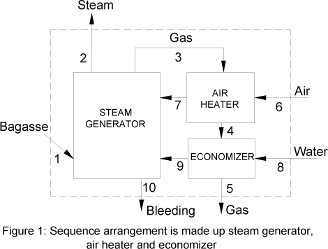
This paper was carried out with some data collected on "Cruz Alta" Plant, which belongs to "Açúcar Guarani" Company, Olímpia, São Paulo State. These data, collected from other members of the staff, were reported in [4].
III. Calculation Methodology
The temperature and pressure parameters of exit boiler steam, used in this work, were the following: P=21 bar, T=320ºC; P=62 bar, T= 480ºC and P=120 bar, T=520ºC. The first two parameters correspond to boilers commercially produced by Equipalcool Industry, whilst the last parameter was considered aiming to analyze the effect of steam temperature and pressure increasing.
3.1 Bagasse composition
Bagasse composition is function of the following factors: cane characteristics, soil type, season, harvest type, extraction method. Baloh and Wittwer [5] compiled bagasse analysis of different authors. They assumed an average composition, which has 47% of carbon, 6.5 % of hydrogen, 44 % of oxygen and 2.5% of ashes (not considered in the formulation, because they do not react). The previous percentages are based on 1 kg of dry mass.
3.2 Bagasse combustion.
The combustion was assumed with air in excess, and since the purpose of this work to perform only an energy balance, generation of CO and NOx, as well as other products as result of incomplete combustion were not considered. The generated substances were determined by the combustion equation. Ideal gas conditions were considered. Air composition was 21 % of oxygen and 79 % of nitrogen (the air humidity was not considered). One kilogram of dry mass of fuel was taken as a base. The balance equation for a stoichiometric combustion is presented in Eq.(1) for stoichiometric conditions and Eq.(2) for air in excess conditions.


The air excess is calculated by Eq. (3), which relates this parameter with the BMC, according [6].

The theoretical and excess air-fuel ratio, AFmolar,theo and AFmolar,exc, are presented in Eq. (4) and (5), respectively:


Where:
nf = nc + nH + no
Therefore, the air excess is related to the BMC:

3.3 Boiler Efficiency
The code ASME PTC 4.1 describes two methods to determine the boiler efficiency: the input-output method and the heat loss method [7].
The boiler efficiency determined by the heat loss method presents values more accurately than the obtained through the input-output method. Also, it permits identify the heat losses that happens in the boiler. Therefore, it is possible to solve problems, improving the boiler efficiency and performance.
In boiler fuelled by sugar cane bagasse is very difficult to measure the cane bagasse mass flow, therefore, to determine the boiler efficiency through the heat loss method is a common practice, and then, with this value in hands, the cane bagasse mass flow [4], [6], [8] and [9].
In this paper were studied two proposals to determine the boiler efficiency: The Beatón and Lora proposal [6] and the code ASME PTC 4.1 proposal [7].
3.6.1 Beatón and Lora proposal: (Proposal I)
In this proposal, the heat absorbed to evaporated the water formed by oxidation of bagasse hydrogen content and also by BMC are discounted in the lower heating value calculation (LHV).
The bagasse lower heating value LHV (kJ/kg) can be determined by the correlation below Eq.(7), proposed by [10].

The physical enthalpy of fuel (qph,b) can be determined by Eq. (8)

Therefore, the available heat from fuel (qa) is:

These authors considered the following heat loss:
(i) Exhaust gases heat losses (q2). Among all heat loss fractions, this is the most significant and it is function of exhaust gas temperature [6]. In the enthalpy calculation of exhaust gas is considered the sensible heat from T à T0. The next equation (10) allows to calculate it:

(ii) Incomplete chemical combustion heat losses (q3)
These losses are related to CO, H2 and CH4 formation, as well as other products resulting of an incomplete combustion. Those elements were previously neglected, thus this loss was done equal to zero.
iii) Heat loss by incomplete combustion due to mechanical causes (q4): is a fraction referred to unburned fuel particles, that go out mixed with the ashes, or are carried by the exit gases. It is calculated by the following equation:

iv). Heat losses due to surface radiation and convection (q5)
The correct way to calculate these losses would be equating all the heat exchanged by convection and radiation from boiler walls to the environment, but, in practice terms, this work is almost impossible, thus a solution for the q5 calculation is to use the ABMA standard radiation loss chart [7], which is based on an average boiler wall temperature, measured by the staff. To use this abacus, its calculation basis (HHV) needed to be taken into account and converted to that used by Beatón and Silva. These authors also presented a chart to determine the radiation and convection boiler heat loss, but it is only function of steam mass flow and does not offered difference when different pressure and temperature of boiler are used. So, it was not utilized.
(v) Heat losses by slag and ashes (q6)
The last lost fraction refers to sensible heat lost by slag and ashes. According [6], this fraction is responsible for less than 0.1 % of the available heat, therefore can be neglected.
The boiler efficiency, obtained through this proposal, is determined from the sum of all heat loss fractions, Eq. (12).

3.6.2 The Code ASME PTC 4.1 proposal: (Proposal II)
This proposal requires the determination of losses, heat credits and the heat credits and ultimate analysis and higher heating value (HHV) of the fuel [7]. It considers the heat losses same than Beatón and Lora proposal (q3, q4, q5, and q6) but the base calculation is the HHV. There are differences in the analysis of boiler exhaust gas heat loss (q2). According ASME PTC 4.1, this heat loss is separated in dried gas heat loss (q2*), heat loss due water vapour from burning hydrogen (q8) and heat loss due BMC (q9).

(vi) Heat loss due sensible heat of dry gas (q2*),

vii) Heat loss due evaporation of water formed from hydrogen in the fuel (q8)

vii) Heat loss due evaporation of water from BMC (q9)

The boiler efficiency, obtained through this proposal, is determined from the sum of all heat loss fractions, Eq. (17).

In this work was considered, for both proposals, besides the heat losses mentioned above, the heat loss by bleeding in boiler (q7). This heat loss was considered corresponding at 2% of boiler steam mass, according [8].
3.3 Air Heater
The inlet cold air temperature was adopted as the average environment temperature, T0=25°C. The boiler exit gases temperature (Tg,3) was determined through the Eq. (18). This parameter was related with the steam saturation temperature (Tsat) at the steam pressure, data of several industrial boilers were analysed and then this correlation was obtained [11]. It was considered that 1.17% of the interchanged heat is lost (Ql,ah), according [12]. The air heater gases exit temperature (Tg,3) was varied between 200°C and 300°C, and boiler inlet air temperature (Ta,1) was determined through pre-heater energy balance Eq. (19), for both methods.

The effectiveness of air heater is defined by Eq.(21).

3.4 Economizer
The inlet water temperature (Tw,6) was adopted as 112°C [12]. The economizer exhaust gas temperature (Tg,4) was considered as 155ºC, which is a very common value in cane bagasse boilers. It was considered that 1.00% of interchanged heat is lost (Ql,Eco). The boiler inlet water temperature (Tw,1) is the unknown variable in the economizer energy balance Eq. (22):

The economizer exergetic efficiency was defined through two types of equations, Eq. (23) and (26). The differences between these equations are the irreversibility due to the gas loss, which was considered outside and inside the economizer control volume, respectively.


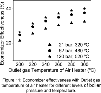
The effectiveness of the economizer can be calculated following Eq. (27).

3.5 Steam Generator
Since several conditions of exit boiler steam temperature and pressure were established; a balance equation as (28) can be written. The steam generator heat loss by radiation and convection (Ql,sg), was determined from the heat loss in whole boiler, determined using the ABMA standard radiation loss chart [7]. The radiation and convection heat loss in the air heater and the economizer were discounted from the total value, obtaining the radiation and convection heat loss for steam generator Eq. (29). The bleed mass flow is determined from the heat loss due bleeding in the boiler (q7). The heat loss by unburned in the steam generator (Ql,unb,mech) is calculated from the heat loss due mechanical problems (q4), Eq. (31). This relationship is obtained from Beatón and Lora proposals and it was applied for both proposals.

The steam generator heat losses are obtained through the Eq. (30)


The steam generator exergetic efficiency is calculated through Eq. (32).

The global exergetic efficiency of boiler is determined trough Eq. (33)

3.7 Exergy of sugar cane bagasse
There are two methodologies to determine the exergy of sugar cane bagasse: The methodology of Szargut et al. (1988) and the methodology of Wittwer (1991). Even though the exergy of sugar cane bagasse is adapted from wood exergy calculation (methodology of Szargut et al. 1988), it is more robust than the methodology of Wittwer [13]. Therefore, the exergy of bagasse was determined through Eq. (35).


IV. Results
As an example, parameters, such as, mass flow, pressure, temperature, enthalpy, entropy and exergy of system fluxes are presented in the Tables I and II for two different situations. These values are presented at temperature gas outlet air heater (Tg,4=200ºC) and steam (P=21 bar) in Table I and (Tg,3=300ºC and Psteam=62 bar) in Table II. The bagasse is considered humid base.
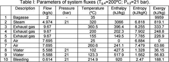
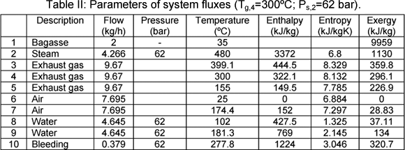
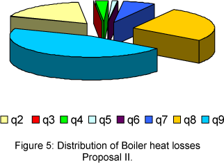
The distribution of boiler heat losses, for proposal I and II are presented in the Fig. 2 and 3, respectively.
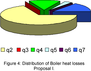
In case of proposal I, the biggest heat loss is represented by the exhaust gas heat loss (q2=9.4%), which corresponds the 68.5% of total heat loss. The other heat losses, such as, that due chemical unburned (q3=0%), mechanical unburned (q4=1.9%), radiation and convection (q5=0.46%), slag (q6=0%) and bleeding (q7=2%) are lower.
In case of proposal II, the biggest heat losses is represented by the evaporation of BMC (q9=14%), the second biggest is due to the evaporation of water vapour formed from hydrogen in the bagasse (q8=8.2%), then comes the heat loss due dry exhaust gas (q2 =5.5 %). The other heat losses, such as, q3= 0%; q4= 0.73%; q5= 0.37% and q6= 0% are lower.
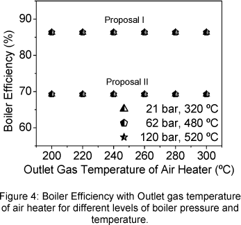
The boiler efficiency, for both proposals, is presented in the Fig. 4. The efficiency of proposal I was higher than that obtained through proposal II, about 25%. In both cases, the boiler efficiency does not vary with the outlet gas temperature of air heater, but varies slowly when exit steam temperature and pressure increase. This happens because that when the boiler output energy increases the proportional radiation and convection heat loss (q5) decreases whilst the others proportional heat loss does not vary.
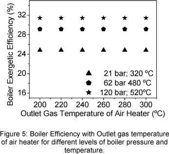
The boiler exergetic efficiency does not vary with the outlet gas temperature of air heater but increases when the steam exit temperature and pressure increase (Fig. 5). The maximum value (31.70%) is observed in the maximum value of steam temperature and pressure whilst the first law boiler efficiency, by both proposals, was 69.2 % and 86.3 %.
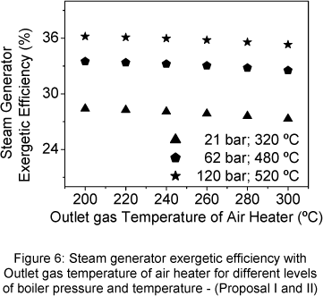
In Fig 6, the steam generator exergetic efficiency decreases slowly with the air heater outlet gas temperature increase. The increase of steam temperature and pressure produces the increase of steam generator exergetic efficiency.
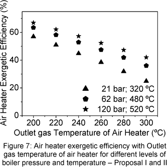
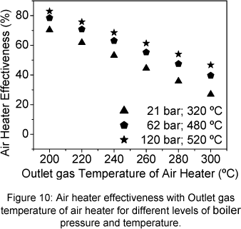
The Fig. 7 shows the air heater exergetic efficiency with the outlet gas temperature of air heater. The air heater exergetic efficiency increase when the outlet gas temperature of air heater decrease. The same behaviour is presented by the air heater effectiveness showed in Figure 10.
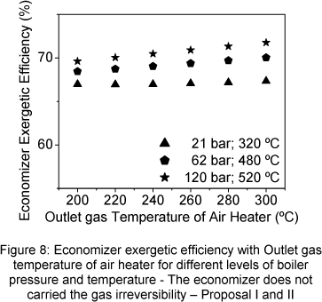
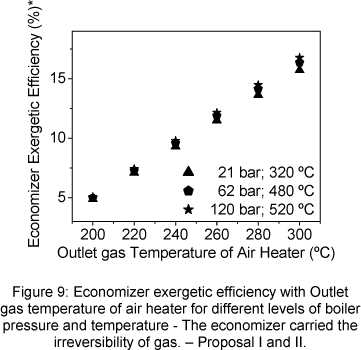
The economizer exergetic efficiency was analyzed through two view points. The first considered that the gas irreversibility, in the economizer outlet, is not carried by economizer (Fig. 8), and the second considered that the gas irreversibility is carried by economizer (Fig. 9).
The economizer exergetic efficiency increases when the outlet gas temperature of air heater increases, the same tendency observed for the effectiveness, (Fig.10 and 11). Exit steam temperature and pressure increasing produce also an increase of the exergetic efficiency. When the economizer carried the gas loss irreversibility, its exergetic efficiency strongly drops (Fig.9).
V Conclusions
The increase of steam temperature and pressure permits to improve the boiler and its peaces of equipment performance and efficiency.
The behaviour of the exergetic efficiency of both heat exchangers, air heater and economizer follows the same tendency as the effectiveness.
The distribution of heat losses according the proposals I and II are different because the base calculation is different. The proposal I discounted in LHV calculation the heat absorbed to evaporate the water formed in the combustion reaction from bagasse hydrogen and also BMC, therefore it is not observed the heat losses by bagasse hydrogen and BMC (q8 and q9) in this proposal. The proposal II highlights these heat losses, which are the bigger in the proportional distribution. The authors recommend the use of the proposal II on the analysis of bagasse boilers since that through this it is easier to decide the improvements aiming the bagasse boilers optimization.
Acknowledges
The authors wish to thank CNPq (Proc. 142135-2003-8; and Proc. 305720/2003-1) and Fapesp (Proc. 2001/14302-1) for their financial support.
VI. REFERENCES
[1] Ibarra, L.R.F., Medellín, A.M.A. Energy saving and cogeneration potential in Mexican sugar mills, Int. Sugar J. 2004 ;Vol. 106, no 1264, pp. 210-221.
[2] Sharma M.P., Sharma, J.D., 1999, Bagasse based Co-generation system for Indian Sugar Mills, Renewable Energy, Vol. 16, pp. 1011 - 1014.
[3] Therdyothin A., Bhattacharya C., Tabucanon M. Evaluation of alternatives to increase the electrical generation capacity of Thai sugar mills, Energy Vol. 17 (1992) No. 3, pp. 247-254.
[4] Sánchez Prieto, M.G., Carril, T.P., Nebra, S.A. Analysis of the Exergetic Cost of the Steam Generation System of the Cruz Alta Mill, In Proceedings of the 16 th Brazilian Congress of Mechanical Engineering 2001, Uberlândia, Brazil, pp. 206 -215 (in Portuguese).
[5] Baloh T., Wittwer E., Energy Manual for Sugar Factories (1995) 200.
[6] Beatón, S.P., Lora E.S. Test of Thermal Balance in Bagasse Steam Boilers, Departamento de Termoenergética, Facultad de Ingenieria Mecánica. I.S.P.J.A.M., Cuba, 1991, (in Spanish).
[7] ASME PCT 4.1. Steam Generating Units. Power test codes, The American Society of Mechanical Engineers, United Engineering Center, New York N.Y. 10017, 1975.
[8] Acosta J. The boiler efficiency fueled bagasse. Int. Sugar J. 1995; Vol. 97, 1158: 248- 255.
[9] Sosa-Arnao J.H., Llagostera, J., Nebra, S.A. Study of operation parameters of power generation systems on sugar cane mills, In Proceedings of the 18 th Brazilian Congress of Mechanical Engineering 2005, Ouro Preto, in CD-ROM.
[10] E. Hugot. Manual for sugar engineers, (1964) 803.
[11] Dalmazo , C.A., 2005, Private Communication, Equipalcool industry.
[12] Sánchez Prieto, M.G., Cogeneration Alternatives in Sugar and Alcohol Factories, Case of Study, Ph.D. Thesis, State University of Campinas (in Portuguese), 2003.
[13] Sosa-Arnao, J. H.; Nebra, S. A. ; The Exergy of Sugar Cane Bagasse; 14th European Biomass Conference & Exhibition: Biomass for Energy, Industry and Climate Protection, 17-21 October, 2005, Palais des Congrès, Paris, France


 Como citar este trabajo